×
Ansys Fluent CFD Analysis — Corning Proculture 500mL Spinner Flask
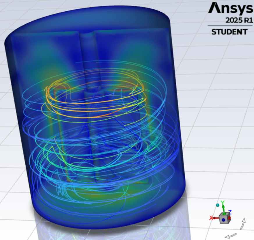
Confidentiality note: The image shown is a representative example based on publicly available geometry. Any CFD data or design details specific to my work at Aspect Biosystems have been excluded to maintain NDA compliance.
Project Overview
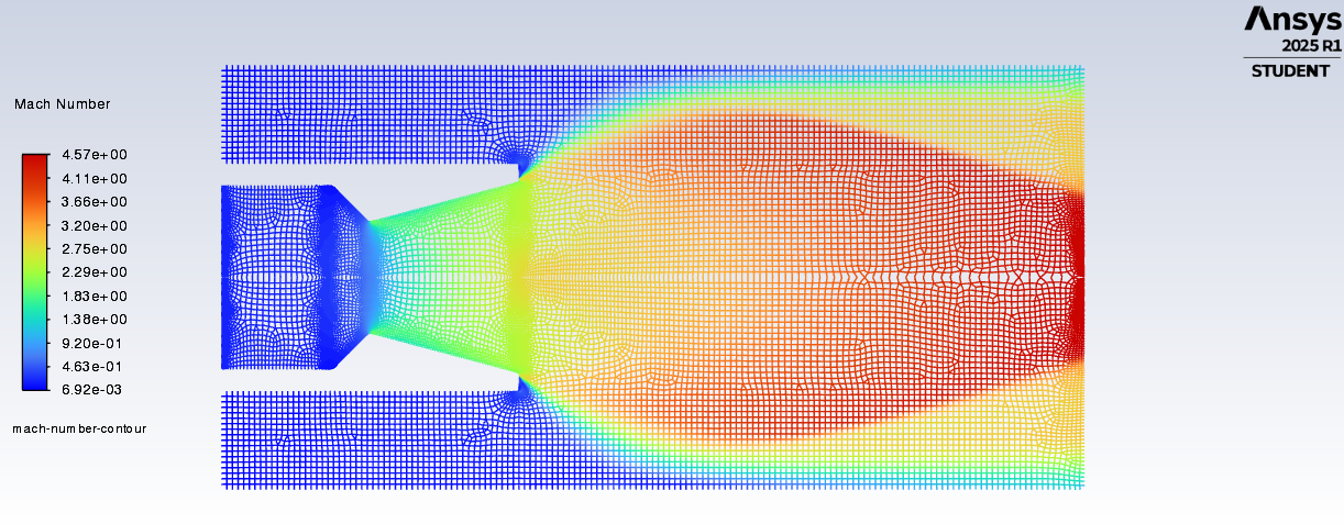
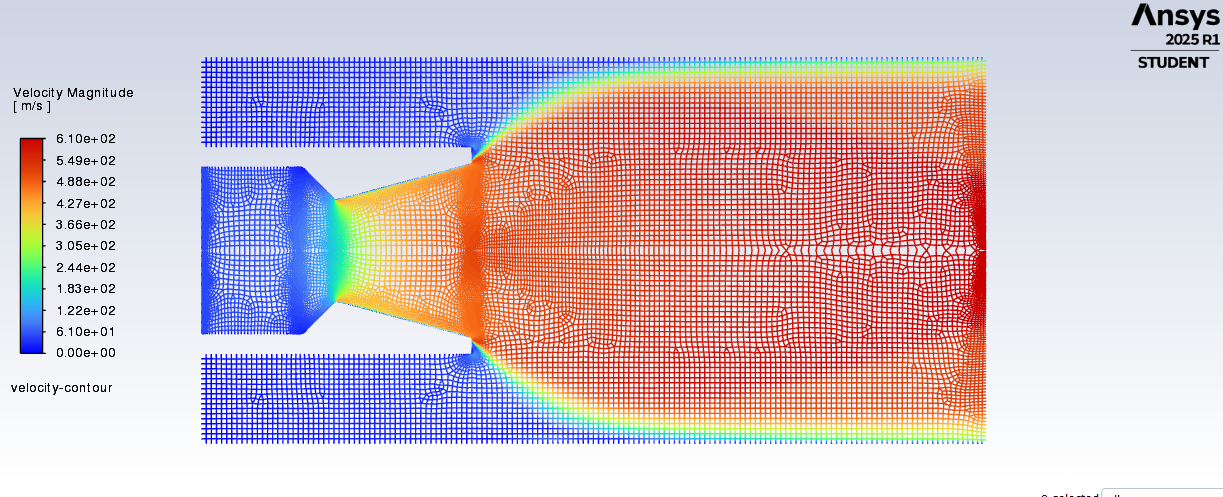
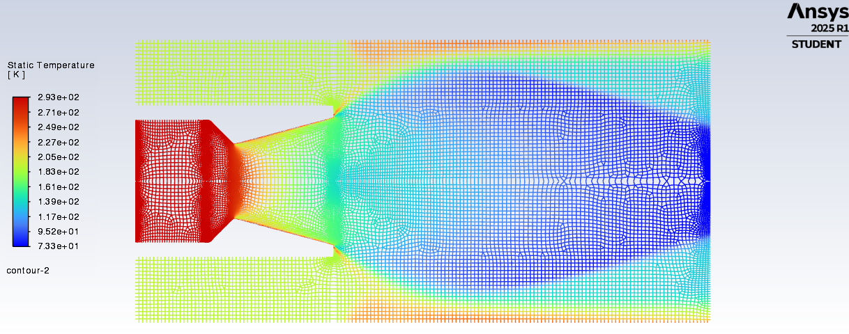
The goal was to characterise the internal shear environment of a Corning ProCulture 500mL disposable spinner flask used for aggregate-based cell culture, and to use that information to identify process parameters that produce equivalent shear profiles across multiple scales. This enabled scale-consistent culture of shear-sensitive cellular spheroids as part of a scalable bioprocess strategy at Aspect Biosystems.
The Challenge
Stirred-tank reactors, particularly paddle impellers, produce highly localized regions of elevated shear and complex flow patterns. Capturing these correctly requires careful geometric representation of the impeller and realistic boundary conditions. The challenge was to predict peak shear regions that correlate with biological outcomes (spheroid viability and morphology) while balancing the computational efficiency and biological accuracy. It was also crucial that the simulations not only converged numerically, but produced physically realistic results.
Roles and Responsibilities
This was a fully independent project conducted end-to-end, involving the following:
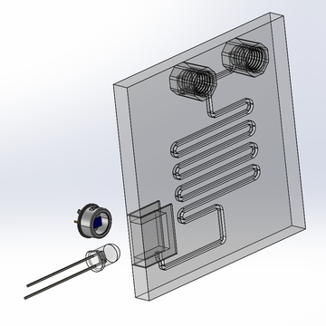
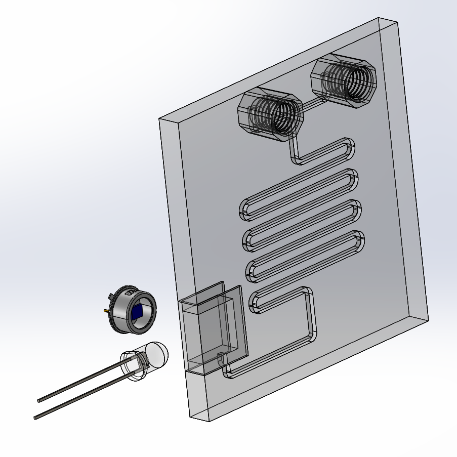
- Preparation of representative CAD: Identified and modeled the critical features of the impeller and internal vessel, modeling them in SolidWorks to accurately represent the drivers of shear generation and propagation.
- Model simplification: Analysed the physical setup and justified simplifications — treated the system as single-phase (assumed minimal phase mixing) and steady-state for the purpose of mapping shear fields efficiently.
- CFD setup: Built the fluid volume mesh and solver setup in Ansys Fluent. Selected turbulence models and solver settings appropriate for high‑Re, impeller‑driven flow and ran simulations to convergence (residuals k <= 1e-3). Gut checks performed with hand calculations to ensure reaslistic results were generated
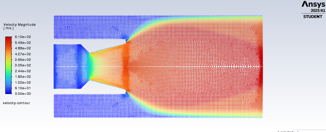
- Post-processing: Computed shear stress (dynamic viscosity × strain rate) and wall shear stress contours on planes and surfaces to locate maximum shear regions inside the vessel.
- Scale testing: Modeled and simulated smaller scale systems in SolidWorks/Fluent to test process parameters and obtain similar shear profiles; designed and conducted wet lab experiments to validate simulation results.
- Process documentation: Drafted descriptive protocols for use of Fluent to rapidly simulate stirred‑tank systems, ensuring knowledge transfer at the end of the engagement.
Outcomes
The CFD analysis successfully identified where peak shear occurs in the spinner flask and allowed rapid in‑silico screening of scale‑up parameters. Using the CFD‑derived parameter sets, lab testing produced spheroid products with consistent morphology across multiple scales, supporting a scale‑consistent manufacturing strategy. The computational approach reduced the need for repeated full‑scale experiments and accelerated the process development timeline.
Takeaways and Learnings
- Geometric simplifications matter. Modeling every detail adds complexity with marginal benefits after a certain point; focus on features that influence key parameters to speed iteration.
- Mesh quality is critical. Though it seems obvious, I saw firsthand how mesh convergence improves shear prediction around the impeller itself
- Practical testing remains essential. Simplified models accelerate iteration but must be validated experimentally to refine parameters, particularly when working with biological systems.
Potential improvements
Given the tight timeline, the model relied on significant geometric simplifications and a single‑phase approach. With more time, I would:
- Implement a transient model to understand shear evolution during impeller start‑up and time‑varying behaviour.
- Introduce two‑phase modeling to assess whether phase mixing meaningfully affects the physics of interest.
- Conduct a full mesh‑independence study to quantify discretization error.
- Evaluate alternative turbulence models (e.g., RSM or k‑ω SST variants) to study sensitivity and improve shear predictions.
- Perform basic uncertainty quantification to evaluate robustness of the simulation.